VxWorks USB HCD Driver Development: OHCI Layer Explained
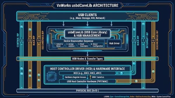
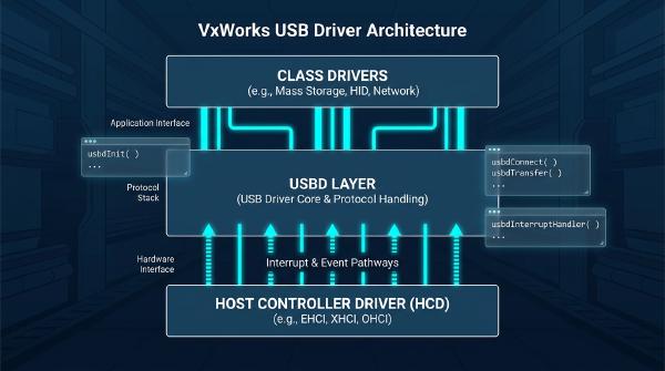
The Host Controller Driver (HCD) is the hardware-facing layer of the VxWorks USB software stack. It sits between the generic USB Driver (USBD) layer and the physical USB host controller, translating standardized USB operations into controller-specific commands.
Understanding the HCD is therefore essential when developing or debugging VxWorks USB drivers.
From the software architecture perspective, the USBD should not need to understand the implementation details of a particular host controller. Instead, it interacts with a standardized HCD interface. The HCD then handles controller-specific operations such as PCI configuration, pipe management, IRP submission, bus state transitions, and scheduling.
This chapter uses an OHCI host controller as the primary implementation example and examines how the HCD layer is organized, how its function libraries interact, and how the generic HCD APIs ultimately reach the OHCI implementation.
🏗️ HCD Layer Architecture #
The HCD layer has two primary responsibilities:
- Control the USB host controller hardware
- Expose standardized interfaces to the USBD layer
From a hardware perspective, a USB host controller can be implemented as a PCI device, much like a PCI network interface controller.
However, there is an important architectural difference.
A network interface controller can have a substantially different programming model depending on its manufacturer. USB host controllers, by contrast, are designed around standardized host-controller specifications such as OHCI and UHCI.
This means that the software does not need to implement a completely different programming model for every controller vendor. Once an OHCI-compliant controller is identified, the driver can implement the OHCI specification and operate compatible hardware.
For the OHCI implementation discussed here, the HCD can be viewed as three functional components:
                    USBD Layer
                        │
                        ▼
              Standard HCD Interfaces
                        │
                 ┌──────┴──────┐
                 │   usbHcdLib │
                 └──────┬──────┘
                        │
                        ▼
                OHCI HCD Implementation
                usbHcdOhciLib.c
                        │
                        ▼
                OHCI Host Controller
                        │
                        ▼
                     USB Bus
The three major components are:
- PCI configuration
- OHCI controller implementation
- Standard HCD interfaces exposed to USBD
🧩 PCI Configuration with usrUsbHcdOhciInit
#
The PCI portion of the OHCI HCD is handled by the usrUsbHcdOhciInit function library.
This library is relatively small and primarily provides the usrUsbHcdOhciAttach entry point.
usrUsbHcdOhciAttach
#
The function performs the initial discovery and attachment of an OHCI host controller.
Its basic sequence is:
- Scan the PCI devices already detected by the system.
- Identify a device matching the OHCI class, subclass, and programming-interface identifiers.
- Read the PCI configuration header.
- Obtain memory-mapped and other controller configuration information.
- Invoke
usbdHcdAttachto attach the HCD implementation to the USB subsystem.
Conceptually, the process looks like this:
PCI Device Enumeration
        │
        ▼
Match OHCI Class/Subclass/PGMIF
        │
        ▼
usbPciConfigHeaderGet()
        │
        ▼
Obtain Controller Resources
        │
        ▼
usbdHcdAttach()
        │
        ▼
Register HCD With USBD
The PCI initialization code therefore provides the bridge between generic PCI device discovery and the controller-specific HCD implementation.
🔌 Standard HCD Interfaces #
The USBD layer communicates with the host controller through a standardized group of HCD interfaces.
This abstraction is important because it isolates the upper USB stack from hardware-specific implementation details.
The HCD exposes the following operations:
usbHcdAttachusbHcdDetachusbHcdSetBusStateusbHcdIrpSubmitusbHcdIrpCancelusbHcdCurrentFrameGetusbHcdPipeCreateusbHcdPipeDestroyusbHcdPipeModifyusbHcdSofIntervalGetusbHcdSofIntervalSet
Although these functions appear to represent the complete HCD interface, their implementations in hcdLib.c are primarily thin wrappers.
The actual controller-specific processing occurs in usbHcdOhciLib.c.
This separation gives the VxWorks USB stack a clean hierarchy:
USBD
 │
 ├── usbHcdAttach()
 ├── usbHcdDetach()
 ├── usbHcdSetBusState()
 ├── usbHcdIrpSubmit()
 ├── usbHcdIrpCancel()
 ├── usbHcdCurrentFrameGet()
 ├── usbHcdPipeCreate()
 ├── usbHcdPipeDestroy()
 ├── usbHcdPipeModify()
 ├── usbHcdSofIntervalGet()
 └── usbHcdSofIntervalSet()
        │
        ▼
   HCD Nexus
        │
        ▼
usbHcdOhciLib.c
        │
        ▼
OHCI Hardware
🧱 Understanding the HCD Request Mechanism #
Before examining the individual interfaces, it is useful to understand the role of HRB_HEADER and HCD_NEXUS.
The generic HCD functions package an operation into an HCD request and then invoke the HCD implementation through the function pointer stored in the nexus structure.
hrbInit
#
LOCAL VOID hrbInit
(
    pHRB_HEADER pHrb,
    pHCD_NEXUS pNexus,
    UINT16 function,
    UINT16 totalLen
)
hrbInit initializes an HRB_HEADER structure.
The header identifies the HCD operation that should be executed and contains information required by the HCD implementation.
Once the request has been initialized, the caller can use:
HCD_NEXUS.hcdExecFuncto dispatch the operation to the controller-specific HCD code.
This design effectively provides a small command-dispatch mechanism between the generic HCD API and the OHCI implementation.
🔗 1. usbHcdAttach
#
STATUS usbHcdAttach
(
    HCD_EXEC_FUNC hcdExecFunc,
    pVOID param,
    USB_HCD_MNGMT_CALLBACK callback,
    pVOID callbackParam,
    pHCD_NEXUS pNexus,
    pUINT16 pBusCount
)
usbHcdAttach establishes the connection between a USB bus and its HCD implementation.
The function receives the HCD execution entry point through hcdExecFunc and uses it to perform the attachment operation.
It also initializes the HCD_NEXUS structure, which stores information needed for subsequent HCD operations, including the execution function pointer and request handle information.
Conceptually:
HCD Attach Request
       │
       ▼
Initialize HRB_HEADER
       │
       ▼
Initialize HCD_NEXUS
       │
       ▼
Call hcdExecFunc()
       │
       ▼
Initialize Controller
Once attachment succeeds, higher layers can use the resulting nexus to access the HCD.
🔌 2. usbHcdDetach
#
STATUS usbHcdDetach
(
    pHCD_NEXUS pNexus
)
usbHcdDetach performs the inverse of the attachment operation.
It uses:
pNexus->hcdExecFuncto dispatch the detach request to the controller-specific HCD implementation.
The operation allows the HCD to release controller-specific resources and disconnect the host controller from the USB subsystem.
⏯️ 3. usbHcdSetBusState
#
STATUS usbHcdSetBusState
(
    pHCD_NEXUS pNexus,
    UINT16 busNo,
    UINT16 busState
)
This function changes the operational state of a USB bus.
The primary states involved here are:
USB_BUS_SUSPEND
USB_BUS_RESUME
The generic HCD layer packages the request and dispatches it through the HCD execution function.
The OHCI implementation then performs the controller-specific operations required to suspend or resume the bus.
🕒 4. usbHcdCurrentFrameGet
#
STATUS usbHcdCurrentFrameGet
(
    pHCD_NEXUS pNexus,
    UINT16 busNo,
    pUINT32 pFrameNo,
    pUINT32 pFrameWindow
)
USB host controllers maintain frame-related timing information that is important for scheduling USB transfers.
usbHcdCurrentFrameGet retrieves:
- The current USB frame number
- The corresponding frame window
The USBD layer can use this information when coordinating operations that depend on USB bus timing.
Frame information becomes particularly important for periodic transfers such as interrupt and isochronous traffic.
📤 5. usbHcdIrpSubmit
#
STATUS usbHcdIrpSubmit
(
    pHCD_NEXUS pNexus,
    HCD_PIPE_HANDLE pipeHandle,
    pUSB_IRP pIrp
)
usbHcdIrpSubmit submits an I/O Request Packet (IRP) to the HCD.
The IRP describes the USB transaction that needs to be performed, while pipeHandle identifies the endpoint configuration through which the transaction should occur.
The general flow is:
USBD
 │
 ▼
USB IRP
 │
 ▼
usbHcdIrpSubmit()
 │
 ▼
HCD
 │
 ▼
OHCI Transfer Structures
 │
 ▼
OHCI Controller
 │
 ▼
USB Device
The OHCI implementation is responsible for translating the generic IRP into the controller-specific scheduling and transfer structures required by the OHCI hardware.
This is one of the most important transitions in the HCD architecture because it converts an abstract USB transfer request into hardware-executable operations.
🛑 6. usbHcdIrpCancel
#
STATUS usbHcdIrpCancel
(
    pHCD_NEXUS pNexus,
    pUSB_IRP pIrp
)
usbHcdIrpCancel requests cancellation of a previously submitted IRP.
The important distinction is that requesting cancellation does not necessarily guarantee that an already executing transfer can be stopped immediately.
Once an IRP has entered the controller’s execution path, its actual cancellation behavior depends on the current state of the transfer and the capabilities of the HCD implementation.
Driver developers therefore need to distinguish between:
- A cancellation request being issued
- The controller actually removing the transfer
- The IRP eventually reaching its completion state
This distinction becomes particularly important when debugging asynchronous USB transfers.
🧵 7. usbHcdPipeCreate
#
STATUS usbHcdPipeCreate
(
    pHCD_NEXUS pNexus,
    UINT16 busNo,
    UINT16 busAddress,
    UINT16 endpoint,
    UINT16 transferType,
    UINT16 direction,
    UINT16 speed,
    UINT16 maxPacketSize,
    UINT32 bandwidth,
    UINT16 interval,
    pUINT32 pTime,
    pHCD_PIPE_HANDLE pPipeHandle
)
usbHcdPipeCreate creates an HCD-level pipe represented by an HCD_PIPE structure.
A USB pipe represents the communication path between the host and a particular endpoint on a USB device.
The parameters describe characteristics such as:
- USB bus number
- Device address
- Endpoint number
- Transfer type
- Transfer direction
- Device speed
- Maximum packet size
- Bandwidth requirements
- Service interval
Periodic transfer bandwidth #
For interrupt and isochronous pipes, the HCD must account for bus bandwidth.
The controller needs to determine whether sufficient scheduling capacity exists before accepting the pipe configuration.
The transfer-time calculation is based on the USB specification.
For an interrupt pipe:
bandwidth = bytes transferred per frameFor an isochronous pipe:
bandwidth = bytes transferred per secondFor control and bulk pipes:
bandwidth = 0If sufficient periodic bandwidth is available, the HCD reserves the required resources for the pipe.
Those resources are subsequently released when the pipe is destroyed.
Service interval #
The interval parameter is relevant to interrupt transfers and represents the maximum service interval.
For example, an interval of 20 ms indicates that the endpoint should be serviced at least once within the corresponding scheduling interval.
The HCD calculates the worst-case packet transmission time and returns the result through:
pTimeThis calculation is important because periodic USB traffic must be scheduled without exceeding the available bus capacity.
🗑️ 8. usbHcdPipeDestroy
#
STATUS usbHcdPipeDestroy
(
    pHCD_NEXUS pNexus,
    HCD_PIPE_HANDLE pipeHandle
)
usbHcdPipeDestroy removes an existing HCD pipe.
The function identifies the pipe through pipeHandle, destroys its associated HCD_PIPE structure, and releases resources allocated to the pipe.
For periodic endpoints, this also includes releasing any bandwidth reservation associated with the pipe.
The lifecycle can therefore be summarized as:
usbHcdPipeCreate()
        │
        ▼
Allocate HCD_PIPE
        │
        ▼
Reserve Required Resources
        │
        ▼
Use Pipe for IRP Transfers
        │
        ▼
usbHcdPipeDestroy()
        │
        ▼
Release Resources
🔧 9. usbHcdPipeModify
#
STATUS usbHcdPipeModify
(
    pHCD_NEXUS pNexus,
    HCD_PIPE_HANDLE pipeHandle,
    UINT16 busAddress,
    UINT16 maxPacketSize
)
A pipe’s device address and maximum packet size can change after the pipe has initially been created.
This situation is particularly relevant to the default control pipe during USB device enumeration.
When a device first connects, the host does not necessarily know all of its final addressing and endpoint characteristics.
The enumeration process can therefore involve:
- Communicating through the default state
- Obtaining device descriptors
- Assigning the device address
- Determining the correct maximum packet size
- Updating the pipe configuration
After the device’s actual address and endpoint parameters are known, both the USBD and HCD layers need to update their corresponding state.
usbHcdPipeModify provides the HCD-level mechanism for making these changes.
⏱️ 10. usbHcdSofIntervalGet
#
STATUS usbHcdSofIntervalGet
(
    pHCD_NEXUS pNexus,
    UINT16 busNo,
    pUINT16 pSofInterval
)
usbHcdSofIntervalGet retrieves the Start-of-Frame (SOF) interval for the USB bus.
The SOF interval represents the timing relationship between consecutive SOF events.
For a typical full-speed USB bus, the nominal frame interval is 1 ms.
The value returned by this API is expressed in units corresponding to the time required to transmit one bit at the relevant bus rate.
For example, at a 12 Mbps full-speed signaling rate:
1 ms × 12,000,000 bits/s
= 12,000 bits
Therefore, a typical SOF interval value is approximately:
12,000This timing information is particularly relevant to periodic transfer scheduling and controller configuration.
⚙️ 11. usbHcdSofIntervalSet
#
STATUS usbHcdSofIntervalSet
(
    pHCD_NEXUS pNexus,
    UINT16 busNo,
    UINT16 sofInterval
)
usbHcdSofIntervalSet configures the SOF interval for the specified USB bus.
Like the other generic HCD functions, the API itself does not directly manipulate OHCI registers. Instead, it packages the request and dispatches it through the HCD execution interface.
The OHCI-specific implementation ultimately performs the hardware-level configuration.
🔄 Putting the HCD Interfaces Together #
The HCD API becomes easier to understand when viewed as a complete USB-controller lifecycle rather than as a collection of unrelated functions.
A typical sequence is:
PCI Discovery
     │
     ▼
usrUsbHcdOhciAttach()
     │
     ▼
usbdHcdAttach()
     │
     ▼
usbHcdAttach()
     │
     ▼
HCD_NEXUS Established
     │
     ├───────────────┐
     │               │
     ▼               ▼
Bus State        SOF Configuration
     │
     ▼
Pipe Creation
     │
     ▼
usbHcdPipeCreate()
     │
     ▼
HCD_PIPE
     │
     ▼
IRP Submission
     │
     ▼
usbHcdIrpSubmit()
     │
     ▼
OHCI Transfer Processing
     │
     ▼
USB Device
     │
     ▼
IRP Completion
     │
     ▼
Pipe Modification / Cancellation
     │
     ▼
usbHcdPipeDestroy()
     │
     ▼
usbHcdDetach()
The important architectural point is that USBD does not need to know how OHCI hardware works.
It only needs to understand the standardized HCD interface.
The HCD implementation handles the translation between those generic requests and the controller’s hardware-specific data structures, scheduling mechanisms, registers, and interrupts.
🧠 Why the HCD Abstraction Matters #
The HCD abstraction provides a clean separation between the USB protocol stack and host-controller hardware.
Without this abstraction, the USBD layer would need separate hardware-specific implementations for every controller architecture.
With the HCD model:
                 USBD
                  │
          Standard HCD API
                  │
       ┌──────────┴──────────┐
       │                     │
      OHCI                  UHCI
       │                     │
   OHCI Hardware         UHCI Hardware
The upper USB stack can remain largely independent of the underlying controller implementation.
For developers working on VxWorks USB drivers, this separation is especially useful when debugging problems. A failure can often be localized to one of several layers:
- PCI layer — controller discovery or resource configuration
- HCD layer — controller initialization and hardware abstraction
- Pipe layer — endpoint configuration or bandwidth allocation
- IRP layer — transfer submission or cancellation
- USBD layer — USB protocol and device management
- Hardware layer — controller, signal, or physical USB problems
Understanding these boundaries makes it much easier to trace a USB transaction from a high-level request down to the actual host-controller hardware.
📚 HCD Layer Summary #
The VxWorks HCD layer is the critical bridge between the generic USBD subsystem and the USB host controller.
For an OHCI implementation, its architecture can be summarized as:
PCI Configuration
      │
      ▼
OHCI Controller Discovery
      │
      ▼
HCD Attachment
      │
      ▼
Generic HCD API
      │
      ├── Bus Management
      ├── Frame Timing
      ├── Pipe Management
      └── IRP Management
              │
              ▼
      OHCI-Specific Driver
              │
              ▼
       Host Controller
              │
              ▼
          USB Bus
The generic functions in usbHcdLib provide the interface contract, while the OHCI-specific implementation in usbHcdOhciLib.c performs the actual hardware operations.
The most important concepts are therefore not the individual wrapper functions themselves, but the layering and request-dispatch mechanism that connects them.
usbHcdAttach establishes the HCD relationship, pipe APIs manage endpoint resources, IRP APIs control data transfers, bus-state functions manage controller operation, and SOF functions provide the timing information required by USB scheduling.
Together, these components form the HCD layer that allows VxWorks to present a consistent USB programming model while supporting different host-controller implementations.
This completes the HCD-layer analysis and establishes the foundation for examining the next level of the OHCI implementation: how the generic HCD requests are translated into OHCI-specific data structures, endpoint descriptors, transfer descriptors, scheduling lists, and controller registers.