VxWorks 6.6 Network Stack and END Driver Architecture
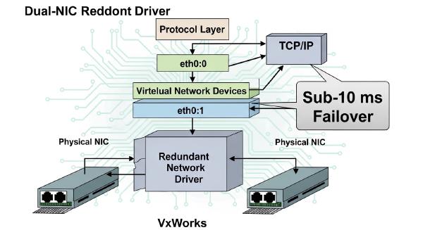
VxWorks 6.6 uses the IPNET/IPCOM networking architecture together with the MUX (Multiplexer) and Enhanced Network Driver (END) frameworks to connect application-level sockets to Ethernet hardware.
Understanding this stack requires following several layers: socket APIs, IPCOM and IPNET, MUX bindings, END driver interfaces, and finally the Ethernet MAC, DMA engine, PHY, and physical link.
This architecture also explains how packet buffers move through the system, how transmit and receive paths are deferred from interrupt context, and why commands such as ifconfig up and ifconfig down primarily manipulate software interface state rather than resetting the underlying Ethernet hardware.
🧩 Ethernet Hardware Interface Fundamentals #
Modern Ethernet controllers separate the Media Access Control (MAC) function from the Physical Layer (PHY). The MAC handles Ethernet framing and packet movement, while the PHY converts digital data into the electrical or optical signaling required by the physical medium.
MAC and PHY Responsibilities #
The MAC is normally implemented inside the Ethernet controller or SoC and is responsible for functions such as:
- Ethernet frame generation and parsing
- Source and destination MAC address handling
- CRC generation and validation
- Flow control
- DMA descriptor management
- Interaction with system memory
The PHY provides the physical-layer functions required to establish and maintain the link, including:
- Signal encoding and decoding
- Serialization and deserialization
- Auto-negotiation
- Link detection
- Physical medium attachment
A typical Ethernet data path is therefore:
Application
    ↓
IP/TCP/UDP
    ↓
Ethernet MAC
    ↓
MAC-to-PHY Interface
    ↓
PHY
    ↓
Physical Medium
MAC-to-PHY Interface Standards #
| Interface | Typical Speed | Primary Characteristics |
|---|---|---|
| MII | 10/100 Mbps | Standard Media Independent Interface |
| RMII | 10/100 Mbps | Reduced-pin MII implementation |
| GMII | 1 Gbps | Gigabit Media Independent Interface |
| RGMII | 1 Gbps | Reduced-pin Gigabit interface using DDR signaling |
| SGMII | 1 Gbps | Serial Gigabit MAC-to-PHY interface |
| XGMII | 10 Gbps | 10-Gigabit MAC interface |
| TBI | Multi-Gigabit | Ten-Bit Interface used in higher-speed designs |
| XAUI | 10 Gbps | Serialized 10-Gigabit attachment interface |
The appropriate interface depends on the MAC, PHY, board design, and target Ethernet speed.
MDIO PHY Management #
Ethernet PHY configuration and status monitoring commonly use MDIO, defined by IEEE 802.3.
Clause 22 provides a traditional management interface using PHY and register addressing and is widely used with conventional 10/100/1000 Ethernet PHYs.
Clause 45 extends the model by introducing explicit device addressing, allowing software to access different PHY subcomponents such as:
- PCS
- PMA
- Auto-Negotiation
- Other managed PHY functions
The distinction becomes important when developing an END driver because PHY initialization, link negotiation, status polling, and low-level register access may all depend on the MDIO implementation.
🏗️ VxWorks 6.6 Network Stack Architecture #
VxWorks 6.6 uses the IPNET/IPCOM networking stack rather than the older BSD 4.4-based architecture.
The high-level path can be represented as:
+------------------------------------------------------------------+
| User Application                                                 |
| socket / bind / send / recv / read / write                      |
+------------------------------------------------------------------+
                              |
+------------------------------------------------------------------+
| sockLib                                                        |
| Socket abstraction and VxWorks I/O integration                  |
+------------------------------------------------------------------+
                              |
+------------------------------------------------------------------+
| IPCOM / IPNET                                                   |
| OS abstraction and IP protocol engine                           |
+------------------------------------------------------------------+
                              |
+------------------------------------------------------------------+
| MUX Layer                                                       |
| muxLib: Protocol-to-END driver binding                         |
+------------------------------------------------------------------+
                              |
+------------------------------------------------------------------+
| END Abstraction                                                 |
| endLib: Standard network driver interface                       |
+------------------------------------------------------------------+
                              |
+------------------------------------------------------------------+
| Ethernet Device Driver                                          |
| MAC / DMA / PHY / interrupt / descriptor management            |
+------------------------------------------------------------------+
                              |
+------------------------------------------------------------------+
| Ethernet Hardware                                               |
+------------------------------------------------------------------+
The key architectural benefit is separation.
IPNET does not need to understand the implementation details of a particular Ethernet controller. The MUX and END layers provide a standardized interface between the protocol stack and hardware-specific driver code.
📦 Network Buffer Management: MBLK and Clusters #
VxWorks networking uses a BSD-style buffer model centered around MBLK structures and associated data storage.
At a conceptual level:
MBLK
 ├── Packet metadata
 ├── Data offset
 ├── Data length
 ├── Link pointer
 └── Cluster / data storage
The data buffer contains packet payload.
A cluster provides a larger memory region that can hold packet data.
The MBLK contains packet metadata and pointers describing where valid data begins and how much data is present. Multiple MBLKs can be chained to represent fragmented packets.
This model supports both contiguous and fragmented packet processing.
Why MBLK Chains Matter #
A packet does not necessarily occupy one physically contiguous memory region.
A chain can instead represent:
MBLK #1 → Ethernet/IP headers
    |
    +→ MBLK #2 → TCP payload
    |
    +→ MBLK #3 → Additional payload
Drivers therefore need to determine whether the hardware DMA engine can consume the existing buffer layout directly.
If it cannot, the driver may need to perform a copy operation into a contiguous DMA-capable buffer.
🚀 Network Driver Initialization Workflow #
Network initialization establishes the relationship between the VxWorks networking stack and the hardware-specific END driver.
A simplified sequence is:
usrNetworkInit()
    |
    └── usrNetEndLibInit()
            |
            ├── muxDevLoad()
            |      |
            |      └── END driver initialization
            |             |
            |             ├── Parse initialization string
            |             ├── Allocate driver control structures
            |             ├── Initialize network buffer pools
            |             └── Register END function table
            |
            └── muxDevStart()
                   |
                   ├── Reset MAC
                   ├── Initialize DMA descriptor rings
                   ├── Connect hardware interrupts
                   ├── Initialize PHY through MDIO
                   ├── Enable Rx/Tx DMA
                   └── Set interface operational flags
For a controller-specific driver such as m5200FecEnd, the initialization routine typically establishes the hardware resources required by the END interface before the device is exposed to the upper network stack.
Driver Control Structures #
The driver normally maintains private state containing information such as:
- MAC register mappings
- DMA descriptors
- Receive and transmit rings
- Interrupt configuration
- PHY state
- Buffer pools
- Interface flags
- END function table
This private state allows the generic MUX layer to interact with the hardware without knowing the controller’s implementation details.
📤 Ethernet Transmission Path #
The transmit path begins with an application operation such as send() or write() and eventually reaches the Ethernet controller’s DMA engine.
A representative flow is:
Application
    |
    └── send() / write()
            |
            └── sockLib
                    |
                    └── ipcom_sendmsg()
                            |
                            └── IPNET
                                 |
                                 └── IP/TCP/UDP processing
                                      |
                                      └── Ethernet output
                                           |
                                           └── muxSend()
                                                |
                                                └── END driver
                                                     |
                                                     └── MAC / DMA
Protocol and Ethernet Header Construction #
IPNET constructs the appropriate network-layer and transport-layer headers before dispatching the packet toward the Ethernet output path.
The MUX layer then associates the packet with the appropriate END interface.
The driver is responsible for preparing the packet for the Ethernet controller and configuring the corresponding DMA descriptors.
Zero-Copy Transmission #
When the packet buffer meets hardware requirements, the driver can potentially use a zero-copy path.
Conceptually:
MBLK payload
    |
    └── DMA descriptor
            |
            └── Ethernet MAC
The DMA engine consumes the existing packet buffer directly rather than copying the payload into another buffer.
This minimizes:
- CPU memory bandwidth
- Packet-copy latency
- Cache traffic
- Per-packet processing overhead
Copy-Based Transmission #
A copy becomes necessary when the existing buffer layout does not satisfy hardware constraints.
Typical causes include:
- Unaligned buffers
- Fragmented MBLK chains
- DMA address limitations
- Hardware-specific buffer-size requirements
- Non-DMA-capable memory
The driver can consolidate the packet into a contiguous cluster before programming the DMA descriptor.
Conceptually:
MBLK chain
   |
   └── Copy
        |
        └── Contiguous DMA buffer
                    |
                    └── DMA descriptor
Transmit Completion #
After the hardware completes transmission, the Ethernet controller raises an interrupt.
Rather than performing extensive packet cleanup directly inside the ISR, the driver can defer processing to a network task.
A representative flow is:
Tx DMA completion
      |
      └── Tx interrupt
            |
            └── Deferred network job
                  |
                  └── Tx completion handler
                        |
                        └── Reclaim descriptors / buffers
This reduces interrupt-context workload and improves system responsiveness.
📥 Ethernet Reception Path #
The receive path operates in the opposite direction.
Before packets arrive, the driver normally prepares a receive descriptor ring containing buffers that the hardware can populate.
When a frame arrives:
Ethernet PHY
    |
    └── MAC
         |
         └── DMA
              |
              └── Rx buffer
                   |
                   └── Rx interrupt
                        |
                        └── Deferred processing
                             |
                             └── END driver
                                  |
                                  └── MUX
                                       |
                                       └── IPNET
                                            |
                                            └── Socket layer
Receive Interrupt #
The hardware generates an interrupt when a packet has been received.
The ISR should perform only the work necessary to acknowledge the event and schedule deferred processing.
For example:
m5200FecRdmaInt()
        |
        ├── Clear interrupt condition
        |
        └── Schedule receive processing
Deferred Receive Processing #
The receive handler executes outside interrupt context and retrieves completed descriptors.
It typically:
- Identifies the completed receive descriptor.
- Obtains the associated packet buffer.
- Constructs or updates the MBLK representation.
- Replenishes the receive ring with a fresh buffer.
- Passes the received packet to the MUX layer.
A representative sequence is:
m5200FecReceive()
    |
    ├── Retrieve completed Rx descriptor
    ├── Build / obtain MBLK
    ├── Replenish hardware Rx buffer
    |
    └── END_RCV_RTN_CALL
             |
             └── MUX
                  |
                  └── IPNET
MUX Protocol Dispatch #
The MUX layer determines which registered protocol handler should receive the Ethernet frame.
The Ethernet type or equivalent link-layer metadata is used to select the appropriate protocol binding.
The packet then moves into IPNET’s receive processing.
Eventually, if the packet belongs to an active socket, the networking stack wakes the corresponding application context waiting in operations such as:
recv()
read()
🔄 ifconfig up/down State Mechanics
#
A common misconception is that:
ifconfig eth0 downnecessarily powers down or resets the Ethernet MAC and PHY.
In the VxWorks 6.6 IPNET architecture, interface state changes primarily operate at the network-stack interface layer.
A simplified path is:
ifconfig
   |
   └── ipnet_cmd_ifconfig()
         |
         └── ipnet_ifconfig_if_change_state()
               |
               └── ipcom_socketioctl()
                     |
                     └── ipnet_eth_ioctl()
                           |
                           ├── Clean interface transmit queues
                           |
                           └── Notify IPNET of interface state
ifconfig down
#
When an interface is brought down, the networking stack can:
- Clear pending transmit queues
- Stop normal protocol-level traffic
- Update interface state
- Notify IPNET that the interface is no longer operational
The relevant state notification is represented by:
IP_EIOXSTOPThe underlying driver object and hardware resources are not necessarily unloaded merely because the IPNET interface has been administratively disabled.
ifconfig up
#
Bringing the interface back up reverses the software state transition.
The stack can:
- Re-enable interface processing
- Validate interface state
- Interact with the MUX layer
- Notify IPNET that the interface is operational
Conceptually:
ifconfig up
    |
    └── IPNET interface state change
          |
          ├── Restore queue processing
          ├── muxIoctl()
          |
          └── IP_EIOXRUNNING
This distinction is important when debugging Ethernet hardware.
An interface being administratively down does not necessarily mean that the PHY has been reset, link negotiation has been restarted, DMA engines have been disabled, or driver resources have been released.
Those operations depend on the specific driver implementation and on how the driver handles interface state transitions.
🧠 Driver, MUX, and IPNET Responsibilities #
The architecture becomes easier to debug when each layer’s responsibilities are separated.
| Layer | Primary Responsibility |
|---|---|
| Application | Socket-based network operations |
| sockLib | VxWorks socket and I/O abstraction |
| IPCOM | OS abstraction and networking services |
| IPNET | IP protocol processing and network interface management |
| MUX | Connects protocol stacks to END drivers |
| END | Standardized network-driver interface |
| Device Driver | Hardware-specific MAC, DMA, interrupt, and PHY control |
| MAC | Ethernet framing and DMA interaction |
| PHY | Physical signaling and link negotiation |
This separation is particularly useful when diagnosing failures.
For example, an application-level timeout does not necessarily indicate an application problem. The failure could exist anywhere between socket processing, IPNET routing, MUX dispatch, driver queues, DMA descriptors, MAC state, PHY negotiation, or the physical link.
🔍 Practical Debugging Strategy #
A systematic debugging approach should follow the packet path rather than immediately modifying the hardware driver.
Application and Socket Layer #
Verify whether the application successfully reaches:
socket()
bind()
connect()
send()
recv()
If the application blocks in recv(), continue downward through the receive path.
IPNET Layer #
Check:
- Interface state
- IP address
- Routing table
- ARP/neighbor state
- Protocol counters
Determine whether IPNET is actually generating or expecting traffic.
MUX and END Layer #
Verify:
- Protocol-to-interface bindings
- END driver registration
- Interface flags
- Driver callbacks
- Packet handoff functions
This identifies failures occurring between the protocol engine and hardware driver.
DMA and Descriptor Layer #
Inspect:
- Tx descriptor ownership
- Rx descriptor ownership
- DMA addresses
- Buffer alignment
- Ring indices
- Completion status
A stuck descriptor ring can prevent otherwise healthy packets from reaching the MAC.
MAC and PHY Layer #
Finally verify:
- MAC enable state
- Rx/Tx DMA state
- MAC address
- Link status
- PHY negotiation
- MDIO register values
- Interface speed and duplex
This bottom-up approach helps distinguish software-stack failures from actual hardware or physical-link failures.
📌 Key Takeaways #
VxWorks 6.6’s IPNET/IPCOM architecture separates protocol processing from hardware-specific Ethernet implementation through the MUX and END frameworks.
The most important architectural relationships are:
- IPNET handles network-layer protocol processing and interface management.
- MUX binds protocol handlers to network interfaces.
- END provides a standardized driver abstraction.
- Ethernet drivers handle MAC, DMA, interrupts, buffers, and PHY management.
- MBLK and cluster buffers provide flexible packet representation and support fragmented data paths.
- Zero-copy transmission can avoid unnecessary packet copies when DMA constraints are satisfied.
- Receive and transmit completion work can be deferred from interrupt context to reduce ISR latency.
ifconfig up/downprimarily changes network-stack interface state and should not automatically be interpreted as a complete hardware reset.- MAC/PHY state transitions depend on the specific END driver implementation, making driver source code essential when diagnosing hardware behavior.
For low-level VxWorks networking work, tracing the complete path from socket() through IPNET, MUX, END, DMA, MAC, and PHY provides a much more reliable debugging model than treating the network interface as a single software component.